
Would you rather record this (unclipped)?

or this (R91 mic preamp going nuts)
A: Providing a higher electret bias voltage, 9V through a 10k resistor to give the mic's fet more headroom. (The R91 provides 2.5V through a 6k8 resistor.)
B: Having much greater preamp headroom, and bypassing the R91's mic
preamp altogether, using a hi-fi or low noise op-amp to go straight into the
line input.
The circuit needs to bring the signal from an electret microphone up to a
level suitable for a line input. Based on measurement of the microphone
output under a range of conditions, I have chosen two gain levels - 2 &
23. 23 is suitable for everyday general recording. 2 is suitable for
live music such as a rock concert. There is a output pot to allow
fine-tuning of the level if necessary, but it is intended that usually the wiper
will be on the land.

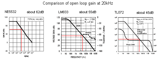
When choosing an op-amp, it's important to find out the open loop gain at 20kHz. The circuit has roughly 27dB of gain, and at least 47dB at 20kHz (i.e. 20dB higher) is desirable. This is because op-amp circuits are predicated on an ideally infinite open loop gain, while in reality 10 times (20dB) higher than the closed loop gain at highest frequency of interest is acceptable. Otherwise the amplifier becomes progressively non-linear. The TL072 at roughly 45dB just makes it. The LM833 is good at Ľ55dB and the NE5532 sparkles at Ľ60+dB.
If you're going for ultra small size, you can build it single supply rail, but an LM833 won't run like that. A TL072 will, with reduced output swing, it'll swing about 1.8VRMS off a single ended 9V supply, which is adequate for the purpose. Otherwise two 9V batteries will do the trick.
Fairly high quality components have been used - 1% metal film resistors, solid aluminium caps, though the output pot is a bit miserable.
Now about these solid aluminium capacitors - in some respects very good capacitors, but I think now I would use 1uF film capacitors as input and output capacitors. They are likely to more closely match the other channel (tighter tolerances), and the golden ear brigade seem to like film capacitors better.
So in summary, it's supposed to have a lot of headroom, be small, quiet,
cheap, have a low part count, somewhere between a battery box and a full fledged
professional box.

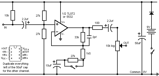
Schematic Of One Channel - Single Rail Version (Slight Difference From
Text)
The leftmost 10k resistor supplies plug-in-power to the electret, forming part of the FET amplifier in the electret capsule. This could be anything from 2k to 10k, the higher the better the stereo separation (another mic derives bias from the same rail). Apparently higher values also lower distortion, and the best bias power circuits involve actually breaking a trace on the electret capsule to allow the use of both a drain & source resistor, but Iím not going that far.
The leftmost 2.2uF cap blocks the bias voltage from the input. In conjunction with the following 27k resistor it forms a high pass filter, but cutoff is essentially near DC.
The input impedance is set by the two 27k resistors and the 10k resistor. The +ve rail is also connected to ground as far as the AC signal is concerned because of the power supply cap. So there are two 27k resistors in parallel, making 13.5k, in parallel with the 10k, making about 6k or so for the input impedance. But if you're making it proper dual supply, you don't need the upper 27k resistor, as the input doesn't have to be biased mid rail anymore.
The feedback loop has two resistors 27k & 1k5 from the inverting input to ground. When they are both in circuit, the gain is a bit under 2 ((28.5/33)+1). The 27k resistor can be bypassed with a switch, then only the 1k5 sets the gain, to 23 ((33/1.5)+1).
The 10uF cap in the bottom half of the feedback loop reduces DC gain to ~1. The value isn't very important. If any DC input offset were amplified it would create a larger output offset, pushing the output toward one of the rails and reducing headroom. (At a gain of 23 with the expected input levels it probably doesn't matter.)
The optional 2pF cap in relation to the 33k resistor sets the high frequency rolloff. The cutoff frequency is in the 100ís of kHz. It has to go further than 20kHz to keep the phase shift at audio frequencies small, and also because output starts falling long before cutoff. The op-amps cannot maintain enough gain at these frequencies anyway and their output will already be falling, but the cap makes the circuit more stable, though it will probably work without it. There will probably be 2pF of capacitance just from the PCB traces, and op-amps tend to be fairly well compensated these days so itís really not needed. I think in retrospect this cutoff frequency should be much lower, say 30kHz-50kHz.
The 100ohm resistors are there partly to limit current to protect the op-amp if the output is shorted, but the op-amps have internal protection anyway. They mainly allow the op-amp to drive capacitive loads (long/cheap cables) without oscillation.
The 2.2uF cap on the output blocks DC and the value is not specially important. It forms a highpass filter with the 10k pot, the cutoff is virtually at DC.
If you think you might accidentally start connecting the battery the wrong
way round, you'd better put a diode in series with the battery clip, or you'll
smoke your ic. Put your ic in a socket too just in case you do want/need to
change it. You could try several dual op-amps against each other, they're all
direct plug in replacements.

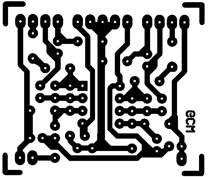
I've not made a stuffing diagram yet, and I probably won't. If you follow the legs from the ic, the components can really only go in one way. Pin 1 is the square hole. Not all of the holes are necessarily used, it depends whether you make it single supply or dual supply and if you include the hf roll-off caps or not. I doubt that anyone will use this circuit layout, but if you do, and you have any questions, please email me. You might want to email me anyway, because there are a couple of (what I shall euphemistically term) issues with this board. It works fine, but having made it, I can see places where it could certainly be improved.
In response to a couple of emails, I updated this a bit. Basically I just changed a couple of holes to fit 0.2" leg spacing on the output capacitors. If I was doing it again from scratch I would try to keep the input tracks further away from the output tracks, but I haven't noticed any instability in this board.
Size - well it's obviously 1mil pin spacing. I scanned it at 300dpi,
and that was a double size image. So if you printed it out at 300dpi,
then told the lithographer to reduce it by a factor of two, it should come out
the right size. But don't take my word for it, check it. When
you've printed it out, measure the pin spacing.
If you're in Australia or NZ, the Dick Smith catalog is a great cheap source of info too.
Berlin, Howard M., 1977, Design of Op-Amp Circuits with Experiments, Indianapolis, Howard W. Sams & Co.
Jung, Walter G., 1975, Audio IC Op-Amp Applications, Indianapolis, Howard W. Sams & Co.
Lancaster, Don, 1975, Active-Filter Cookbook, Carmel Indiana, SAMS Prentice Hall Computer Publishing
Malmstadt, H., Enke, C., Crouch, S., 1981, Electronics and Instrumentation
for Scientists, Menlo Park CA, Benjamin/Cummings
![]() Get your own Free Home
Page
Get your own Free Home
Page